Assembly
Valve train:
Rocker arm assemblies are cleaned in a tumbler before thoroughly inspected for wear at the tip and the rocking area. Rocker arm shafts will be checked for wear and, like rocker arm assemblies, replaced with new if wear will be present. Push rods will be replaced with new regardless.
Cylinder head bolts:
Head bolts will always be replaced with new if torque-to-yield kind. All other head bolts will be cleaned with a rotating wire brush and checked for length and diameter to exclude stretch due to previous over-torque.
After each individual component has been rebuilt the engine will finally be reassembled before being tested for oil pressure and compression on our spin tester.
First, new camshaft bearings will be installed into the block with a special cam bearing installation tool. Bearings will be checked for proper clearance and roundness with a precision micrometer and dial bore gauge once installed and recorded in the installation sheet. The camshaft will carefully be installed and rotated to ensure straightness and proper bearing alignment.
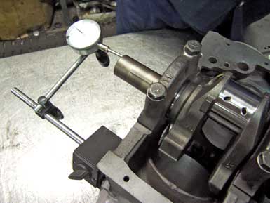
Main and rod bearings will be installed and all caps torqued to specs before also checked for proper clearance and roundness with a precision micrometer and dial bore gauge and recorded in the installation sheet. The commonly known checking procedure with a so-called plastic gauge does not comply with professional standards as it will not reveal out-of-roundness. The crankshaft will carefully be installed and rotated to ensure straightness and proper bearing alignment before checking and recording endplay with a magnetic base dial gauge. All threads will be lubed to ensure proper torque specs.
Piston ring gap will be checked with feeler gauges by inserting the rings into the cylinders equally aligned about one inch below the upper edge. Tight gaps will cause excessive cylinder wear and possible piston seizing. Tight ring gaps must be corrected by filing the ring ends in a special ring filing device. Wide ring gaps will cause compression leaking into the crank case (blow-by). Wide ring gaps cannot be corrected and are subject to replacement.
Varying ring gaps are always related to the manufacturing process and must be checked and recorded in the installation sheet before installation on the new pistons.
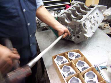
Now the piston and connecting rod assemblies will be installed into the block with a special assembly lube applied to rings, pistons and cylinder walls using a special ring compressor tool to avoid damage. The same assembly lube is used on main-, rod-and Cambearings. Piston-to-wall clearance has already been verified and recorded during the bore-and honing process. Damage to the crankshaft will be avoided using rubber sleeves on all rod studs.
The crankshaft endplay check will be repeated once piston installation is complete and endplay of each connecting rod on the crank journal has been checked. A magnetic base dial gauge will be used to measure and record the distance from the piston bottom to the block deck surface. This is a very important checking procedure to verify equal compression height on all cylinders. Finally the crankshaft will be rotated several times to ensure integrity.
Engines with camshaft in block will be assembled with new timing chain, crankshaft-and camshaft sprocket. Possible existing chain guides and tensioners will also be replaced with new parts.
Subsequently the remanufactured cylinder head(s) will be installed. Lubricated head bolts will equally hand tightened before torqued in order to specs in several steps. Thread sealant instead of lubricant will be applied to head bolts ending in water passages. High temperature silicone will be added below bolt head as extra safety measure to avoid water leaks.
Engines with overhead camshafts will now receive new timing belt/chain, new sprockets, new guides and new tensioners.
Finally new hydraulic lifters, push rods and rocker arm assemblies will be installed on engines with camshaft-in-block design.
Engines with adjustable rocker arms require setting the hydraulic lifter preload: First the valve train will be installed relatively loose with the firing order divided in two equal sequences with four cylinders each. On a four stroke engine two pistons will always be at top-dead-center (TDC) simultaneously. The crankshaft will be rotated by hand until the rocker arms on cylinder one overlap closing the intake valve while opening the exhaust valve simultaneously. The twin piston at TDC, also the first cylinder in the second firing order sequence will now have both valves fully closed ready for adjustment: both rocker arm nuts will be carefully bolted down until all clearance between push rod, hydraulic lifter plunger and rocker arm is eliminated. An additional 180 degree turn at the rocker arm nut will set the desired lifter preload. Rotating the crankshaft 90 degree clockwise will bring the second cylinder in the firing order in overlap TDC and the sixth cylinder in the firing order (second cylinder in second firing order sequence) in TDC with both valves fully closed ready for adjustment. This procedure will be repeated until lifter preload on all eight cylinders is adjusted.